
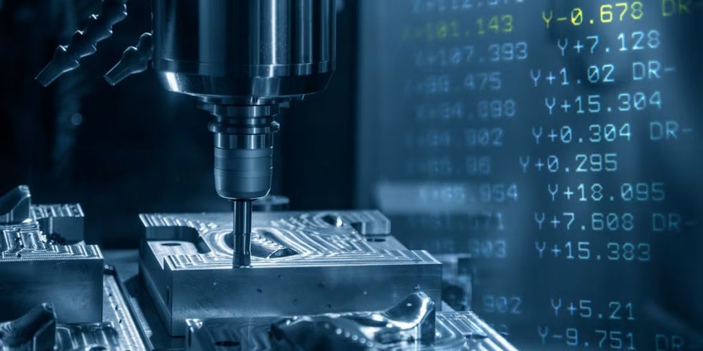
Every part produced on a CNC machine begins with a series of precise instructions called G-code. This language tells the machine exactly how to move, cut, and shape material into the desired form.
The Language Behind CNC
When you look at a finished part produced on a CNC machine, it's easy to admire the craftsmanship. But behind every cut, every curve, and every drilled hole, there is a language telling the machine exactly what to do. That language is G-code.
Think of G-code like a musical score: it doesn't make music itself, but it tells the pianist which keys to press, how long to hold them, and at what tempo. Similarly, G-code gives CNC machines the detailed "sheet music" they need to transform raw material into precise parts.
Though developed in the 1950s, G-code remains the universal standard in CNC machining today. Despite variations across brands like Haas, Fanuc, or Siemens, the fundamentals are shared industry-wide.
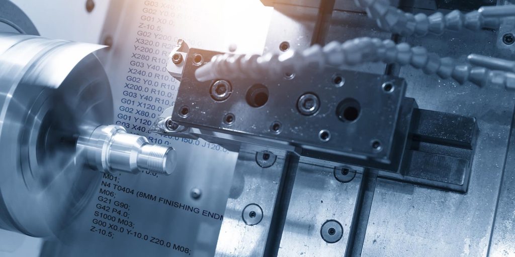
What Is G-Code?
At its core, G-code is a programming language for CNC (Computer Numerical Control) machines. It describes tool movements, speeds, positioning, and cutting operations in a way the machine can understand. Two categories of codes are most important:
- G-codes: “Geometry codes” that control motion and positioning.
- M-codes: "Machine codes" that manage machine functions such as spindle direction, coolant on/off, or tool changes.
A typical CNC program is a sequence of blocks (lines of code), each containing instructions. For example:
G01 X50 Y20 F200 T01 M03 S1500
This single line tells the machine:
- Move in a straight line (G01)
- To coordinates X=50, Y=20
- At feed rate F200
- Using Tool #1 (T01)
- Start spindle clockwise (M03)
- Set spindle speed to 1500 rpm (S1500)
Another key feature is modal commands: once a G-code is set, it stays active until another code replaces it. For example, after G01 is activated, the machine remains in "linear cut" mode until told otherwise. We will break down an example to make it easier to read later on.
The History of G-Code
G-code dates back to the earliest days of numerical control (NC) machines in the 1950s, when the U.S. Air Force sponsored research into automated part production. Before G-code, machining instructions were punched into paper tapes as sequences of numbers, a primitive but revolutionary method for its time.Â
The formalized G-code language (RS-274) emerged soon after as a standardized way to tell machines how to move, cut, and shape parts. In other words, G-code was created as a "common language" for machine tools, ensuring that different machines could interpret commands consistently. This standardization is what allowed CNC machining to evolve rapidly into the global custom manufacturing backbone it is today.
From RS-274 to Modern Variants
While the original RS-274 remains the foundation, G-code has branched into numerous dialects. Every major CNC machine manufacturer – from Haas and Fanuc to Siemens and Heidenhain – implements the standard slightly differently.Â
For example, a Fanuc controller might use certain canned cycles with subtle syntax differences compared to a Haas machine, even though both are "speaking" G-code. This creates what machinists sometimes call "flavors" of G-code. Despite these variations, the structure is recognizable: commands always begin with a letter (like G, M, X, Y, Z, F, S) followed by a number or value.Â
Over time, these variants have added convenience features, making G-code more powerful without straying too far from its original RS-274 logic.
Conversational Programming and CAM Software
Although G-code remains the backbone of CNC machining, modern shops don't always program parts line by line anymore. Many machinists use conversational programming, where the operator inputs high-level instructions directly into the machine (e.g., "drill a hole of this diameter here"), and the CNC control automatically generates the underlying G-code.Â
Similarly, computer-aided manufacturing (CAM) software such as Fusion 360 or Mastercam has become widespread. CAM software allows engineers to design toolpaths visually and then export them as G-code, ready to be read by a CNC machine.Â
Even in these cases, the final step is still G-code — it remains the "machine language" that every CNC tool must understand, regardless of how user-friendly the interface looks on the surface.
Why G-Code Still Matters Today?
Despite decades of evolution and alternatives, G-code continues to be indispensable.Â
- It is a transparent language: machinists can read and debug it line by line, which is critical when troubleshooting errors or fine-tuning precision operations.Â
- It is universal: virtually every CNC machine can interpret G-code, even if the syntax varies slightly between brands.Â
- Understanding G-code gives machinists a direct grasp of how the machine interprets motion, feeds, and speeds.
In an era where automation and CAD/CAM are prevalent, the ability to "speak" G-code ensures manufacturers can still optimize performance, prevent costly mistakes, and push CNC technology to its limits. G code is important for:
- Precision: Micron-level accuracy for aerospace, medical, and automotive components.
- Efficiency: Well-optimized programs reduce tool wear and cycle time.
- Flexibility: From CNC milling and CNC turning to laser cutting and even 3D printing, G-code is adaptable across processes.
- Compatibility: Despite being over 60 years old, it remains the common standard worldwide.
Get an instant quote from Xmake by uploading your design file today, and enjoy fast, reliable delivery with our expert manufacturing services.
Start a QuotePractical Tips to Learn G-Code
For newcomers or professionals looking to sharpen their skills, here are practical steps:
- Start with core codes – G00, G01, G02, G03.
- Use simulation software (like Fusion 360, Mach3, or NC Viewer) to test code safely before machining.
- Read your machine's manual – different controllers (Fanuc, Haas, Siemens) have their own dialects.
- Gradually explore advanced features like canned cycles, offsets, and macros.
Common G-Codes Explained

At first glance, G-code can look intimidating, a wall of letters and numbers. In reality, most machining relies on a handful of essential commands.
| G-Code | Meaning | Common Use Case | Example Command | What Happens |
| G00 | Rapid positioning | Quickly move between cutting locations | G00 X0 Y0 | Tool moves at max speed to (0,0) without cutting. |
| G01 | Linear interpolation | Straight-line cutting at a set speed | G01 X50 Y25 F150 | Tool cuts a straight path to (50,25) at 150 mm/min. |
| G02 | Circular interpolation (CW) | Cutting clockwise arcs or circles | G02 X30 Y10 R5 | Tool follows a clockwise arc with 5 mm radius. |
| G03 | Circular interpolation (CCW) | Cutting counterclockwise arcs | G03 X30 Y10 R5 | Tool follows a counterclockwise arc. |
| G17 / G18 / G19 | Plane selection | Defines XY, XZ, or YZ working planes | G17 | Circular moves now apply in XY plane. |
| G20 / G21 | Unit selection | Program in inches (G20) or millimeters (G21) | G21 | Switches units to millimeters. |
| G54–G59 | Work coordinate systems | Set part origins or multiple fixtures | G54 | Activates first work offset, useful for multiple parts. |
How to Read G-Code: A Step-by-Step Guide
Letters like X, Y, Z define axis positions, F sets feed rate, S controls spindle speed, and T selects the tool. Each block of code tells the machine where to move, how fast to move, and what tool behavior to follow.
Step 1: Recognize the structure of G-code
G01 X10 Y20 F150
This block has:- G01 – type of motion (cutting move)
- X10 Y20 – coordinates of where the tool will move
- F150 – feedrate (speed of tool movement)
Step 2: Spot the "G" command first
- G00 – rapid positioning (fast move, no cutting)
- G01 – linear interpolation (cutting move in a straight line)
- G02 – clockwise arc
- G03 – counter-clockwise arc
G01 X50 Y25
- Translation: Move in a straight line to position X=50, Y=25.
Step 3: Read the coordinates (X, Y, Z)
These tell the machine where the tool should go. X and Y control horizontal movement. Z controls vertical movement (depth).
Example:
G01 X100 Y0 Z-5
- Â Translation: Cut a line to (100,0), while lowering the tool to 5 mm below the surface.
Tip: Negative Z values mean the tool is cutting into the material.
Step 4: Notice the feedrate and spindle commands
- F = feedrate, how fast the tool moves through the material (mm/min or in/min).
- S = spindle speed, how fast the tool rotates (RPM).
Example:
G01 X50 Y25 F200 S1200
- Translation: Cut straight to (50,25) at a speed of 200 mm/min, with the spindle rotating at 1200 RPM.
Step 5: Look for setup commands at the beginning
Programs usually start with preparation code.
Common examples:
- G20 – use inches
- G21 – use millimeters
- G17 – select XY plane
- G90 – absolute positioning (coordinates based on origin)
Example:
G21 G90
- Translation: Use millimeters, and measure all positions from the fixed origin point.
Step 6: Identify the end of the program
CNC programs end with special commands:
- M30 – stop program and rewind
- M02 – end of program (no rewind)
Example:
M30
- Translation: Program complete, reset the machine to the beginning.
Step 7: Put it all together
G21Â Â Â Â (Work in millimeters)
G17Â Â Â Â (XY plane selected)
G90Â Â Â Â (Absolute positioning)
G00 X0 Y0Â (Rapid move to origin)
G01 X50 F200Â (Cut straight to X=50 at feedrate 200)
G01 Y50 Â Â Â (Then cut upward to Y=50)
G00 Z10 Â Â Â (Retract tool to safe height)
M30 Â Â Â Â Â (End of program)
Translation:
- Use millimeters, XY plane, absolute coordinates.
- Start at the origin (0,0).
- Cut a line 50 mm to the right.
- Then cut a line 50 mm upward.
- Lift the tool 10 mm above the part.
- Stop the program.
This creates a simple "L" shaped toolpath.
Even without prior coding experience, the logic is readable: move to start, plunge, cut four edges, retract.
Advanced G-Code Features
While basic G- and M-codes handle most machining, advanced functions provide more efficiency and flexibility:
- Canned Cycles (e.g., drilling, tapping)
Commands like G81 or G84 automate repetitive tasks. Instead of writing multiple lines for a drilling sequence, a canned cycle executes the operation with just one line of code. - Subroutines & Macros
Allow for loops, conditional statements, and parameterized machining. This is especially useful for parts with repeating features. - Comments & Notes
Operators can include remarks (in parentheses or after semicolons) to make code easier to read.
For example:
G01 X30 Y10 F100 (Cut side wall)
Complete CNC G-Code List
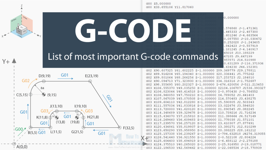
While most machinists rely on a small set of codes daily, there are dozens of G-codes that control specific functions. Below is a more comprehensive list. (Note: Availability may vary depending on the CNC controller brand, e.g., Fanuc, Haas, Siemens.)
| G-Code | Function | Notes / Use Case |
| G00 | Rapid positioning | Fast, non-cutting moves |
| G01 | Linear interpolation | Controlled cutting move |
| G02 | Circular interpolation, CW | Clockwise arcs |
| G03 | Circular interpolation, CCW | Counterclockwise arcs |
| G04 | Dwell | Pause for a set time |
| G05 | High-precision cycle | Sometimes "HPCC" for smoother paths |
| G06 | Parabolic interpolation | Rare, used for complex curves |
| G07 | Cylindrical interpolation | For wrap-around cutting on cylinders |
| G08 | Acceleration control | Machine-specific |
| G09 | Exact stop check | Forces stop at end of block |
| G10 | Programmable offsets | Set work offsets or tool data |
| G11 | Cancel offset values | Clears G10 settings |
| G12 | Circular pocket milling, CW | Mill a pocket clockwise |
| G13 | Circular pocket milling, CCW | Mill a pocket counterclockwise |
| G14–G15 | Reserved / Spindle orientation | Depends on controller |
| G16 | Polar coordinate interpolation | Useful for lathe/live tooling |
| G17 | XY plane selection | Default plane for arcs |
| G18 | XZ plane selection | For turning and vertical arcs |
| G19 | YZ plane selection | For special cases in milling |
| G20 | Programming in inches | Imperial units |
| G21 | Programming in millimeters | Metric units |
| G22 | Stored stroke limit ON | Define axis travel limits |
| G23 | Stored stroke limit OFF | Cancel limits |
| G24 | Reserved / not standard | Controller-specific |
| G25 | Spindle speed clamp | Safety limit on RPM |
| G26 | Thread cutting cycle (lathe) | Used in turning operations |
| G27 | Machine zero return check | Confirm machine reference point |
| G28 | Return to machine home | Sends axes to home position |
| G29 | Return from home | Return via intermediate point |
| G30 | Return to secondary home | Alternative machine zero |
| G31 | Skip function (probing) | Used in probing cycles |
| G32 | Single-thread cutting | Threading one pass |
| G33 | Spindle synchronized motion | For threading cycles |
| G34 | Variable pitch threading | Rare use case |
| G35 | Fixed pitch threading | For constant thread pitch |
| G36–G37 | Automatic acceleration / deceleration | Controller-specific |
| G38.x | Probing cycles | Common in 3D probing, e.g. G38.2 |
| G39 | Circular interpolation, end at angle | Single-arc cut |
| G40 | Cancel cutter radius comp. | Reset compensation |
| G41 | Cutter radius comp. left | Offset tool left of path |
| G42 | Cutter radius comp. right | Offset tool right of path |
| G43 | Tool length compensation (+) | Apply tool length offset |
| G44 | Tool length compensation (–) | Less common |
| G45 | Tool offset increase | Adjust offsets dynamically |
| G46 | Tool offset decrease | Fine adjustments |
| G47 | Tool offset double increase | Â |
| G48 | Tool offset double decrease | Â |
| G49 | Cancel tool length compensation | Â |
| G50 | Spindle speed clamp (lathe) | Limits RPM on lathes |
| G51 | Scaling function ON | Scale programmed moves |
| G52 | Temporary work offset | Local coordinate shift |
| G53 | Machine coordinate system | Overrides work offset |
| G54–G59 | Work coordinate systems | Define multiple part setups |
| G60 | Single direction positioning | Improves accuracy |
| G61 | Exact stop check mode | Stops at each block end |
| G62 | Automatic cornering | Rounds sharp corners |
| G63 | Tapping cycle | Rigid tapping |
| G64 | Cancel exact stop check | Default cutting mode |
| G65 | Simple macro call | Run custom macros |
| G66 | Modal macro call | Macro stays active |
| G67 | Cancel modal macro | Â |
| G68 | Coordinate rotation | Rotate program plane |
| G69 | Cancel rotation | Reset plane rotation |
| G70 | Finishing cycle | Lathe finishing |
| G71 | Stock removal cycle (turning) | Roughing cycle |
| G72 | Finishing cycle (turning) | Finishing pass |
| G73 | High-speed drilling cycle | Peck drilling |
| G74 | Peck drilling / tapping (lathe) | Reverse spindle |
| G75 | Peck grooving cycle | Lathe grooving |
| G76 | Thread cutting cycle | Automated threading |
| G77 | Reserved | Â |
| G78 | Boring cycle (lathe) | Â |
| G79 | Canned cycle, special | Controller-specific |
| G80 | Cancel canned cycle | Resets to normal mode |
| G81 | Drilling cycle | Simple drill |
| G82 | Drilling cycle with dwell | Drill and pause |
| G83 | Peck drilling cycle | Deep hole drilling |
| G84 | Tapping cycle | Â |
| G85 | Boring cycle, feed in/out | Â |
| G86 | Boring cycle, feed in/spindle stop/rapid out | Â |
| G87 | Back boring cycle | Â |
| G88 | Boring cycle, dwell, spindle stop, manual retract | Â |
| G89 | Boring cycle, feed in/out with dwell | Â |
| G90 | Absolute programming | Uses absolute coordinates |
| G91 | Incremental programming | Uses relative moves |
| G92 | Position register / spindle clamp | Multi-purpose |
| G93 | Inverse time feed rate | Used in 5-axis |
| G94 | Feed per minute | Standard milling feed |
| G95 | Feed per revolution | Standard lathe feed |
| G96 | Constant surface speed (CSS) | Lathe mode |
| G97 | Cancel CSS (fixed RPM) | Â |
| G98 | Return to initial plane | Drilling cycles |
| G99 | Return to R plane | Drilling cycles |
(This table intentionally broadens beyond just "common codes" to act as a reference hub — not every shop will use them all.)
Conclusion
Despite its age, G-code continues to power the manufacturing world. It's the invisible hand guiding every precise movement in CNC machining. While newer standards like STEP-NC are being explored for richer, data-driven manufacturing, G-code remains the common ground for machinists everywhere.
In essence, G-code is not just a set of commands. It's the bridge between digital design and physical reality, enabling ideas on a screen to become tangible, functional parts.
For fast, expert CNC machining and instant online quotes, check out Xmake – one of the leading online CNC machining companies.