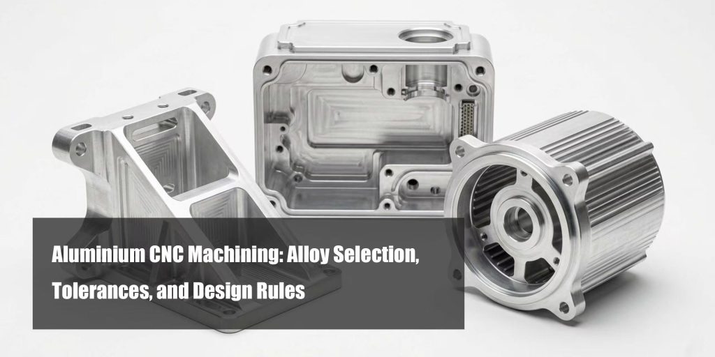
Choosing the right aluminum alloy for CNC machining isn't just about strength — it's about cost, machinability, and production efficiency. While 6061-T6 is often preferred for its ease of machining and lower cost, 7075-T6 offers higher strength at the expense of longer machining time, increased tool wear, and higher overall cost. The wrong choice can lead to unnecessary expenses or performance risks.
This guide will help you choose the right aluminum alloy, understand achievable tolerances, and make design decisions that reduce cost without compromising performance.
I. Alloy Selection: The Decision Behind the Quote
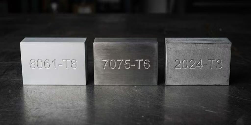
The three grades engineers most frequently specify — 6061-T6, 7075-T6, and 2024-T3 — aren’t interchangeable. Each has a defined performance envelope, and selecting outside it creates problems downstream that no machining operation can fix.
6061-T6 is the baseline for structural aluminum in most commercial and industrial applications. Its tensile strength of 310 MPa and yield of 276 MPa cover brackets, enclosures, heat sinks, structural frames, and most prototype parts where loading isn’t extreme. It welds cleanly, anodizes with consistent cosmetic results, and machines at high speeds without excessive tool wear — which keeps per-part costs lower.
7075-T6 carries a tensile strength of 572 MPa — nearly double 6061. The tradeoff is poor weldability, moderate corrosion resistance without coating, and a harder cutting behavior that increases tooling cost per part. Specify 7075-T6 when your stress analysis shows 6061 approaching yield under combined loading, or when weight reduction under high load is a primary design constraint. Drone frames, aerospace brackets, and tooling jigs are the natural territory.
2024-T3 sits in a specific niche: fatigue-critical structures under repeated cyclic loading. Its 483 MPa tensile strength and superior fatigue resistance make it standard in aircraft skins and riveted airframe structures. Corrosion resistance is low — 2024 must be clad or coated in any exposed application. Machinability is good but not as clean as 6061, and weldability is poor.
Material Grade Comparison: 6061 vs 7075 vs 2024
We provide a simple table for these three materials to help you make comparisons.
| Property | 6061-T6 | 7075-T6 | 2024-T3 |
|---|---|---|---|
|
Tensile Strength |
310 MPa |
572 MPa |
483 MPa |
|
Yield Strength |
276 MPa |
503 MPa |
345 MPa |
|
Hardness (Brinell) |
95 HB |
150 HB |
120 HB |
|
Machinability |
Excellent |
Good |
Good |
|
Weldability |
Excellent |
Poor |
Poor |
|
Corrosion Resistance |
Good |
Moderate |
Low |
|
Anodizing Quality |
Excellent |
Good |
Moderate |
|
Relative Cost |
$ |
$$$ |
$$ |
|
Best For |
General structural, enclosures, prototypes |
High-load aerospace, tooling, jigs |
Fatigue-critical aerospace, riveted structures |
Pro Tip — Default to 6061-T6 unless stress analysis specifically rules it out. 6061-T6 covers 80%+ of structural enclosure and bracket applications, machines faster (lower tool wear = lower per-part cost), and anodizes predictably. 7075-T6 is the right call when yield strength exceeds 300 MPa under combined loading — not before.
Achievable Tolerances in Aluminium CNC Machining
Tolerance specification is where most files are over-engineered — and where most unnecessary cost enters a quote.
Standard machining practice on 6061-T6 aluminum with 3-axis CNC milling holds ±0.1 mm across most features without special setup. If your enclosure walls, mounting hole patterns, and pocket depths all call for ±0.1 mm, that’s a clean, cost-efficient job. Tighten to ±0.025 mm for features that mate with press-fit inserts or need precise assembly alignment. For bearing bores, precision shafts, or tight slip fits, CNC turning reaches ±0.005 mm — but that requires datum fixturing and intermediate inspection steps that add lead time.
Pro Tip — Tolerance grades should match function, not aspiration. A bracket with M5 clearance holes doesn’t need positional tolerance tighter than ±0.1 mm. A motor housing bore receiving a bearing with an H7/p6 press fit needs ±0.015 mm or better. Specifying the first at ±0.015 mm doesn’t improve the part — it increases setup cost with zero functional return.
7075-T6 and tolerancing: 7075 machines slightly harder than 6061 due to its higher hardness (150 HB vs 95 HB). Tight tolerances are achievable — CNC turning on 7075 holds ±0.005 mm — but expect 10–20% higher tooling consumption compared to equivalent 6061 operations. This is relevant on large production runs where tool change frequency affects cycle cost.
Thermal effects: Aluminum has a coefficient of thermal expansion of approximately 23.6 µm/m·°C. On a 300 mm aluminum part, a 5°C ambient temperature swing introduces 35 µm of dimensional change. For parts holding tolerances tighter than ±0.02 mm, machining environment temperature and part temperature at inspection both need to be controlled. Flag this to your supplier when submitting tight-tolerance drawings.
Aluminium CNC Machining Tolerances by Process
| Process | Standard Tolerance | Tight Tolerance | Surface Finish (Ra) | Best For |
|---|---|---|---|---|
|
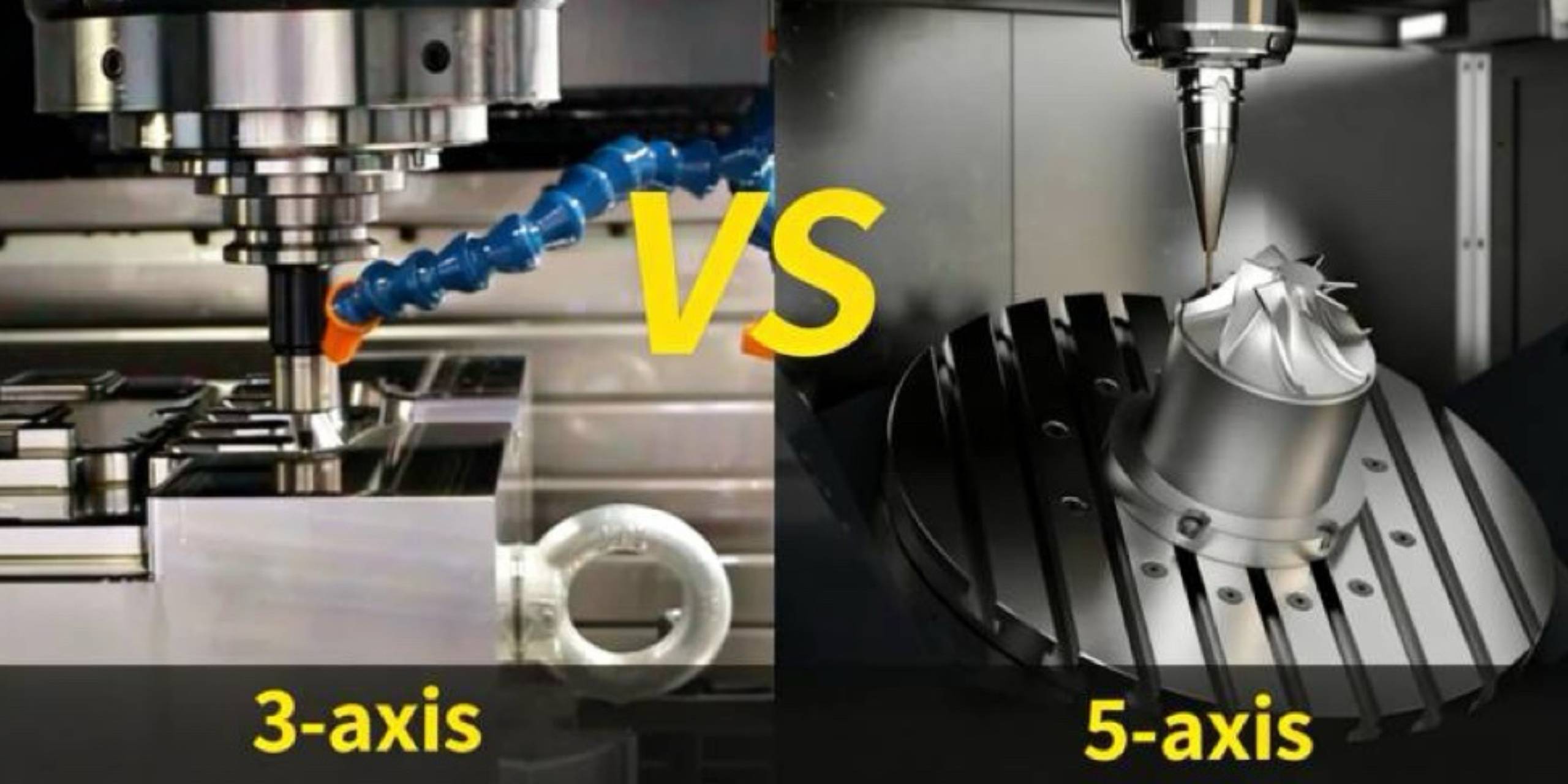
3-Axis CNC Milling |
±0.1 mm |
±0.025 mm |
1.6–3.2 µm |
Flat features, pockets, slots |
|
4/5-Axis CNC Milling |
±0.05 mm |
±0.01 mm |
0.8–1.6 µm |
Compound angles, undercuts |
|
CNC Turning |
±0.025 mm |
±0.005 mm |
0.4–1.6 µm |
Cylindrical shafts, bores |
|
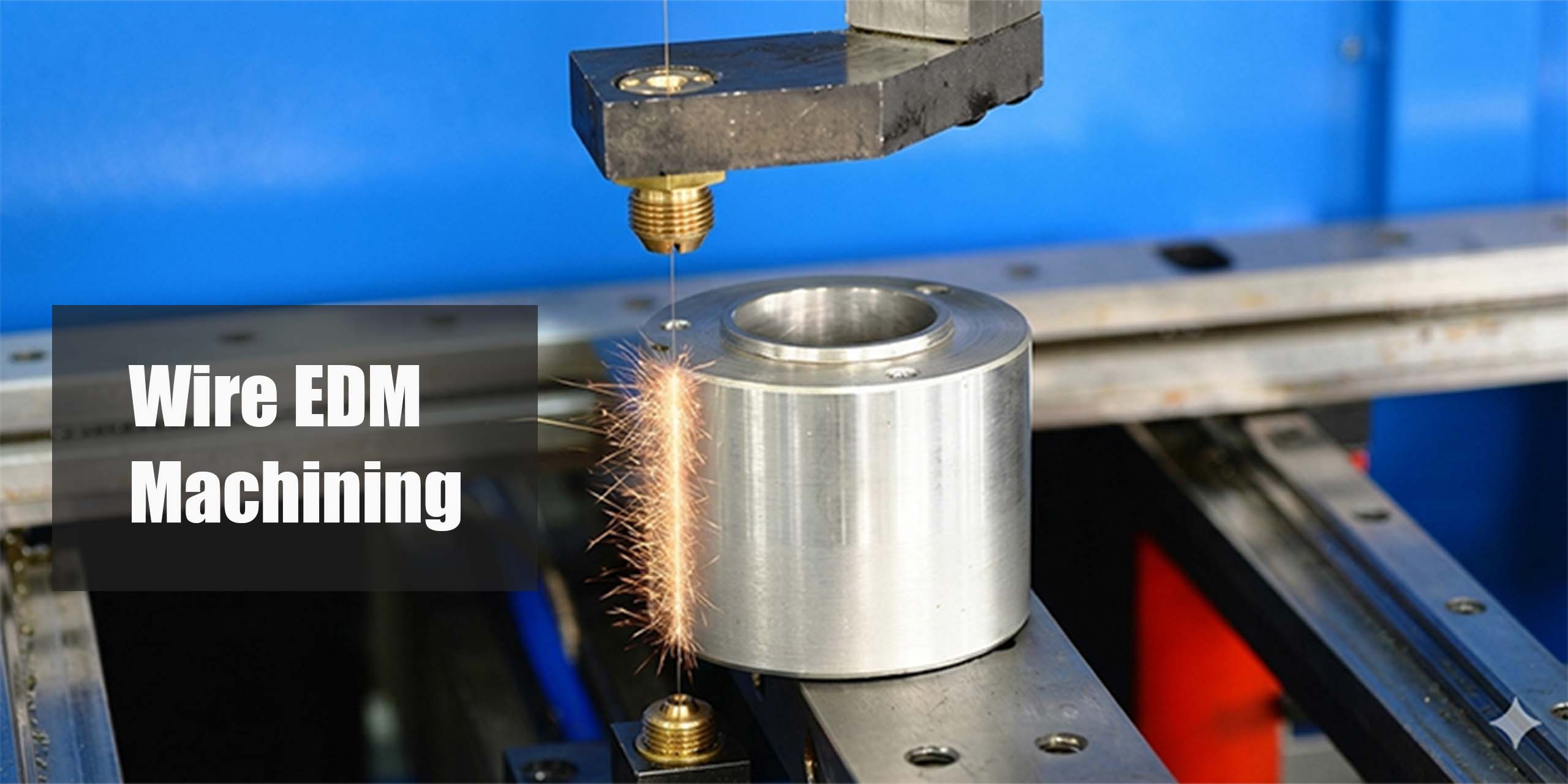
Wire EDM |
±0.01 mm |
±0.005 mm |
0.4–0.8 µm |
Thin walls, hardened features |
|
Content |
±0.005 mm |
Sub-micron |
0.1–0.4 µm |
Bearing seats, precision bores |
Surface Finishes for Aluminium CNC Parts
Surface finish selection affects corrosion performance, cosmetic result, dimensional hold, and downstream assembly compatibility — not just appearance.
Anodizing (Type II) is the standard finish for aluminum enclosures and structural parts. It builds a controlled oxide layer of 5–25 µm thickness, improving corrosion resistance without meaningful dimensional change. 6061-T6 anodizes with consistent color and texture. 7075-T6 anodizes reliably but can show slight color variation due to higher zinc content. 2024 anodizes poorly — if cosmetic finish matters on 2024 parts, consider alclad versions or alternative coatings.
Hard Anodizing (Type III) builds a layer up to 25–75 µm thick, significantly increasing surface hardness to 400–600 HV. The dimensional addition is real — typically 12–25 µm per surface — and must be accounted for in tight-tolerance features. Bores and shafts that need post-anodize dimensional accuracy require pre-anodize stock allowance on the drawing.
Sandblasting prior to anodizing removes machining marks and produces a uniform matte texture. It adds Ra 2.5–5 µm surface roughness and is primarily cosmetic — it does not improve corrosion resistance on its own.
Electroplating (nickel, gold) is used on aluminum for EMI shielding applications and contact surfaces. Adhesion requires a zincate pre-treatment step, which adds process time but produces reliable bonding on 6061 and 7075.
| Finish | Thickness Added | Hardness Gain | Best Use Caseh |
|---|---|---|---|
|
Type II Anodize |
5–25 µm |
Moderate |
Enclosures, structural parts |
|
Type III Hard Anodize |
25–75 µm |
High (400–600 HV) |
Wear surfaces, sliding components |
|
Sandblast + Anodize |
Per above |
Per above |
Cosmetic matte finish |
|
Electroplating (Ni) |
5–25 µm |
Moderate |
EMI shielding, contact surfaces surfaces |
|
Powder Coat |
Powder Coat |
Low |
Non-precision exterior surfaces |
Engineering Heuristic: If any feature requires dimensional accuracy after anodizing, add a note to the drawing: “Anodize all surfaces except [feature] — mask and machine bore post-anodize.” This prevents the anodize layer from consuming your bore tolerance allowance.
Design Checks Before You Send Your Files
Running these checks before submitting for quote eliminates the most common DFM feedback loops and prevents first-article rejections.
Wall thickness minimums.
For 3-axis milling in 6061-T6, minimum supported wall thickness is 0.8 mmfor short walls (under 10 mm height) and 1.5 mm for walls over 25 mm. Thinner walls vibrate during cutting and deflect under tool pressure, producing tolerance failures even when the machine is calibrated correctly.
Internal corner radii.
Every internal corner on a milled pocket needs a radius — the tool is round. Match internal corner radius to the tool diameter you expect to be used: r = 0.5 × tool diameter, minimum 0.5 mm. Sharp internal corners require EDM or are simply unmachineable with standard milling tools. If your design has sharp internal corners, either add the radius in CAD or accept that the supplier will need EDM, which adds cost.
Depth-to-width ratio on pockets.
Deep, narrow pockets require long-reach tools with reduced rigidity. Standard practice limits depth to 4× the pocket widthfor milled features. Beyond that, chatter marks appear on walls and bottom surface finish degrades. If the design requires deeper pockets, flag it explicitly and ask for the supplier’s tool reach capability.
Thread specifications.
Specify thread standard, pitch, and depth on every threaded hole — never leave it to the supplier to infer. M4×0.7, M5×0.8, M6×1.0are the standard metric thread pitches for aluminum. Minimum thread engagement in aluminum should be 1.5× the nominal diameter (e.g., 7.5 mm engagement depth for M5). Undersized engagement in aluminum strips under torque — a failure mode that appears during assembly, not inspection.
Tolerance callout discipline.
Apply GD&T or explicit bilateral tolerances to every critical feature. Leaving features without explicit tolerance defaults to your supplier’s general machining tolerance — which may be ±0.1 mmor may be ±0.5 mm depending on their standard. Never assume.
Material certification requirement.
If your application is aerospace (AS9100D), automotive (IATF 16949), or medical (ISO 13485), state the material certification requirement on the drawing header. Mill cert (Certificate of Conformance)is a standard procurement requirement — request it explicitly or it may not be included in delivery documents.
XMAKE’s engineering team provides free DFM analysis on every uploaded file — catching wall thickness violations, corner radius issues, and tolerance conflicts before the job goes to a machine.
Aluminium CNC Machining Price: What Drives Your Quote
Machine time is the primary cost driver. 6061-T6 machines at higher cutting speeds than 7075-T6 or 2024-T3 — typically 15–25% faster on equivalent operations — which directly reduces cycle time per part. On a 100-part production run, that speed differential accumulates into a meaningful cost gap.
Setup complexity is the second driver. A part that machines complete in one setup on a 5-axis center costs less per unit than a part requiring three separate 3-axis setups with intermediate repositioning and re-inspection. Design for minimum setups: orient critical features to a single datum face where possible, and consolidate toleranced features to one side of the part.
Tolerance tightening adds disproportionate cost at the extreme end. Going from ±0.05 mm to ±0.025 mm on a bore might add 10% to the operation cost. Going from ±0.025 mm to ±0.005 mm can add 40–80% — because it requires intermediate inspection steps, temperature-controlled measurement, and potentially grinding rather than milling as the final operation.
Surface finish requirements add post-processing cost that is often underestimated on quotes. Hard anodizing with masking on specific features, electroplating with zincate pre-treatment, or multi-step cosmetic finishing (sandblast + anodize + laser marking) each add 20–60% to the base machining cost on a typical enclosure. Quote these processes separately from machining if you need to manage budget against a target.
Conclusion
Alloy selection and tolerance specification are decisions made at the drawing stage — both determine machinability, post-processing options, and final part cost before a single machine turn runs. Getting the grade and tolerance bands right before submitting files eliminates DFM cycles and first-article failures.
XMAKE operates CNC machines across two workshops in Baoan, Shenzhen, running 24/7 with tolerances to ±0.01 mm on 6061-T6 aluminum. Lead times start at 3 day for simple geometries . Upload your file for a quote now.
Frequently Asked Questions
What is the tightest tolerance achievable on 6061-T6 aluminum with CNC turning?
CNC turning on 6061-T6 reaches ±0.005 mm on diameter under controlled conditions — datum fixturing, coolant, and calibrated tooling. Achieving this repeatably across a batch requires intermediate inspection and temperature-stable measuring conditions. For most bearing fits, ±0.01–0.015 mm is the practical specification range.
Is 7075 aluminum harder to machine than 6061?
7075-T6 machines well but is harder (150 HB vs 95 HB for 6061-T6), which increases tool wear per unit. Cutting speeds are typically reduced 10–15% versus 6061 equivalent operations. For short prototype runs, the cost difference is minor. On production volumes above 500 parts, the tooling cost differential becomes a meaningful line item.
what surface finish does CNC-milled aluminum have as-machined?
Standard 3-axis milling on 6061-T6 produces an as-machined surface of Ra 1.6–3.2 µm. 5-axis finishing passes achieve Ra 0.8–1.6 µm. If your application requires a cosmetic or functional finish below Ra 0.8 µm, specify CNC grinding or lapping as a secondary operation.
Does anodizing change the dimensions of a machined aluminum part?
Type II anodizing adds 5–25 µm per surface (2.5–12.5 µm per side on a bore). For clearance fits and non-critical exterior surfaces, this is negligible. For precision bores with H7 tolerance or tighter, the anodize layer will consume part of the tolerance band. Either machine the bore post-anodize, or add stock allowance pre-anodize and confirm the final dimension in the surface finish specification.
What alloy should I use for an aluminum part that also needs to be welded?
6061-T6 is the correct choice for welded aluminum assemblies. 7075-T6 and 2024-T3 are both rated poor for weldability — fusion welding causes hot cracking in the heat-affected zone. If the design requires welded joints in high-strength aluminum, consult a structural engineer to evaluate whether 6061 with thicker section meets the load requirement before specifying a non-weldable alloy.
What is the minimum wall thickness for CNC-milled aluminum?
For 3-axis milling in 6061-T6, supported wall minimum is 0.8 mm for short features (under 10 mm height). Unsupported or tall walls should be 1.5 mm minimum to avoid vibration-induced surface defects. 7075-T6 behaves similarly. If the design requires walls below 0.8 mm, sheet metal fabrication or EDM is a more appropriate process.
How do I specify aluminum CNC machining tolerances on my drawing?
Apply explicit bilateral tolerances (e.g., ±0.05 mm) to every dimension where fit or function depends on it. Use ISO 2768-m (medium) as a general tolerance standard for non-critical features — state it in the drawing title block. For critical mating features, apply GD&T callouts: positional tolerance, cylindricity, and perpendicularity as appropriate. Never leave critical dimensions without explicit tolerance.