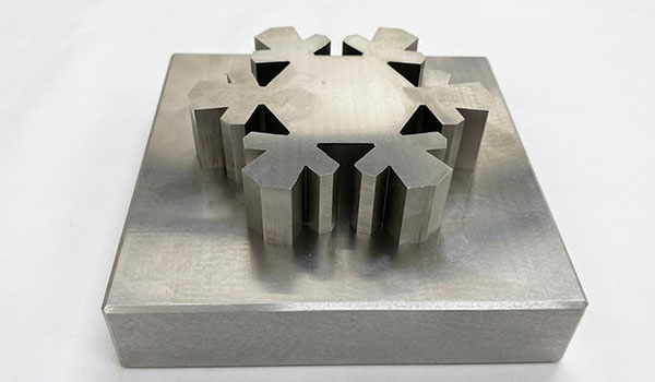
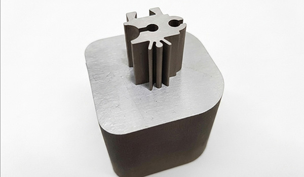
When your design drawings involve extremely small internal angles (e.g. ≤0.15 mm), fabricators will often recommend employing Wire EDM to achieve this feature.This is because traditional CNC machining is limited by tool diameter and cannot machine truly acute-angled features; wire EDM, however, removes material through electrical discharge, fundamentally overcoming the limitations on internal corner radii. Geometric features such as ultra-small internal angles and acute-angled contours all require wire EDM for machining.
This guide provides a systematic overview of the machining principles, suitable materials, tolerance capabilities, cost factors and key design considerations for wire EDM, to help you determine whether this process is suitable for your parts.
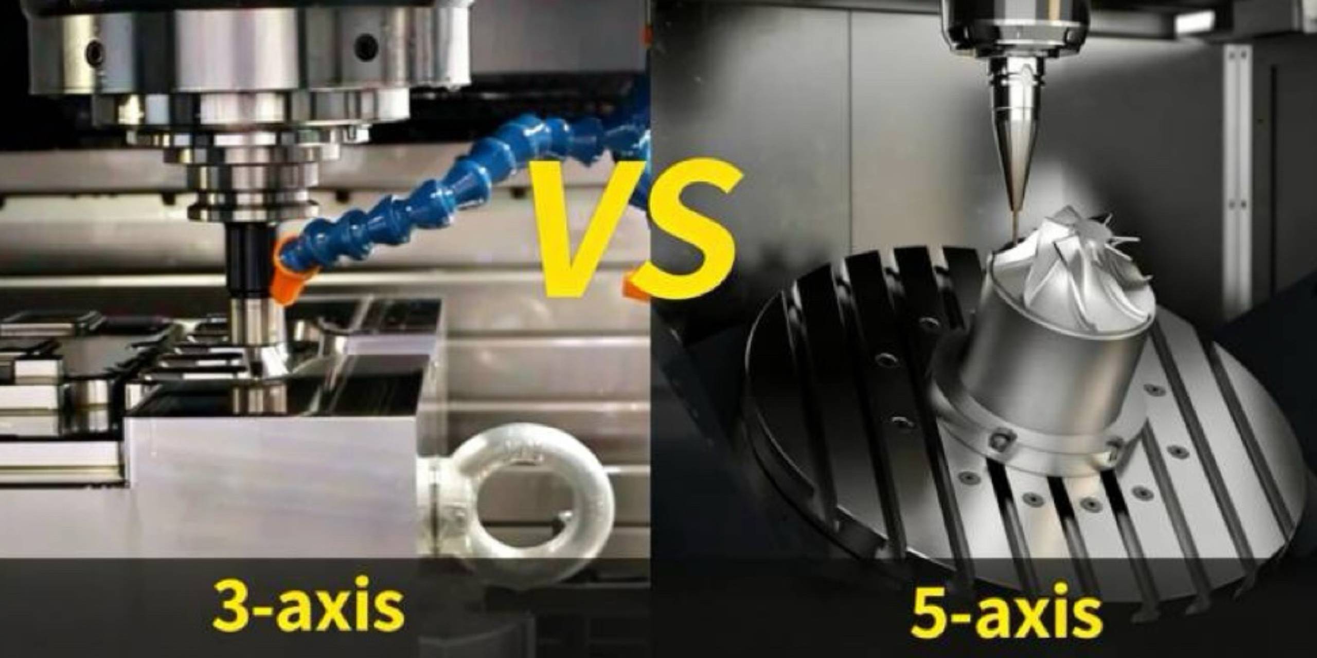
Process Comparison: Wire EDM vs CNC Milling vs CNC Turning
Before committing to a process, the table below provides a decision-level view of the three most common precision machining options (Wire EDM, CNC Milling, CNC Turning).
| Attribute | Wire EDM | CNC Milling | CNC Turning |
|---|---|---|---|
|
Suitable Materials |
Any electrically conductive material — hardened steels, carbide, titanium, copper, brass, Inconel |
Metals, plastics, composites |
Round-section metals and plastics |
|
Min Internal Corner Radius |
~0.13mm (wire diameter dependent) |
~0.4mm (limited by smallest end mill) |
Not applicable (external geometry) |
|
Tolerance |
±0.003–±0.005mm (fine wire) |
±0.01–±0.05mm |
±0.005–±0.02mm |
|
Surface Finish Ra |
0.2–1.6 µm (multi-pass) |
0.4–3.2 µm |
0.4–1.6 µm |
|
Cost Range |
$$–$$$ (high per-hour rate, no fixturing cost) |
$–$$ (scales with complexity and setups) |
–– –$ (efficient for cylindrical parts) |
|
Best For |
Hard materials, sharp corners, tight tolerances, thin features, no cutting force |
Prismatic parts, pockets, 3D surfaces |
High-volume cylindrical parts, threads, bores |
The key practical takeaway: Wire EDM is not a speed process. It excels when geometry or material hardness makes conventional cutting either impossible or prohibitively expensive due to tooling wear and rework.
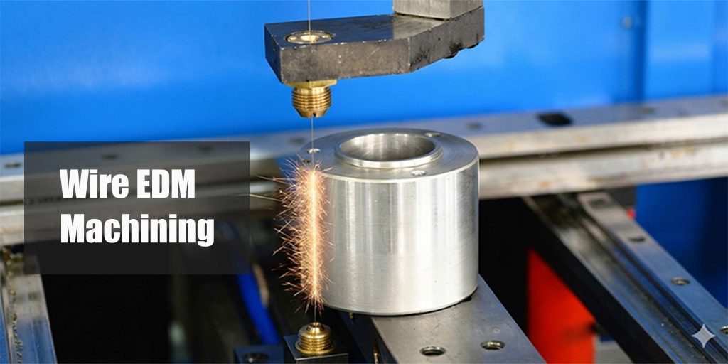
How Wire EDM Works
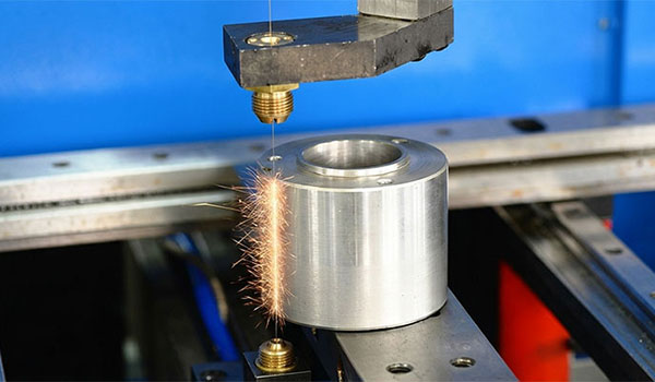
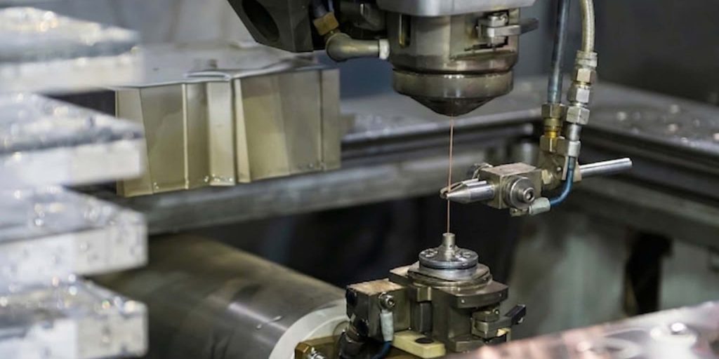
Wire EDM (Wire Electrical Discharge Machining) removes material through controlled electrical spark erosion — not mechanical cutting. A thin brass wire, typically 0.1–0.3mm in diameter, is fed continuously through the workpiece while a pulsed electrical current generates sparks across a small gap (usually 0.01–0.05mm) filled with deionized water.
Each spark removes a microscopic amount of material from the workpiece surface. The wire never contacts the part directly, which means cutting force is effectively zero. This is the core reason Wire EDM works on hardened materials that would deflect, chatter, or break conventional cutting tools.
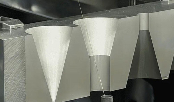
The machine controls four axes as a minimum — X, Y, U, V — allowing the wire to tilt and produce tapered cuts or complex prismatic features in a single setup.
Engineering Heuristic: If your part is already hardened before machining begins, Wire EDM is almost always the right process. CNC milling hardened D2 (62 HRC) destroys carbide end mills within minutes. Wire EDM cuts D2 at 62 HRC with the same reliability as annealed mild steel — hardness is irrelevant to the process.
Wire EDM Material Reference Table
The table below covers the materials most commonly processed on Wire EDM, with achievable tolerance and surface finish by material type.
| Material | Typical Grade | Achievable Tolerance | Notes |
|---|---|---|---|
|
Tool Steel |
D2, H13, M2 |
±0.003–±0.008mm |
Hardened state preferred; minimal distortion vs heat treatment |
|
Titanium |
Ti-6Al-4V (Grade 5) |
±0.005–±0.01mm |
Reactive metal — proper flushing critical to prevent recast layer buildup |
|
Copper / Brass |
C11000 copper, C26000 brass |
±0.005–±0.01mm |
Excellent conductivity; common for EDM electrodes and connectors |
|
Stainless Steel |
304, 316, 17-4 PH |
±0.005–±0.01mm |
Austenitic grades cut well; PH grades produce good Ra |
|
Inconel |
Inconel 718 |
±0.005–±0.01mm |
Very slow cutting rate; cost-effective vs trying to mill at full hardness |
|
Aluminum |
6061-T6, 7075-T6 |
±0.008–±0.015mm |
Wire EDM is rarely cost-optimal for aluminum — CNC is usually faster |
Pro Tip — Recast Layer: Every Wire EDM pass leaves a recast (re-solidified) layer of 2–15 µm depending on power settings and number of passes. For fatigue-critical aerospace or medical parts, specify a final skim cut pass at low energy settings. This reduces the recast layer to under 2 µm and brings Ra down to 0.2–0.4 µm. If your drawing does not specify recast layer requirements, your supplier will default to the economical 2-pass cut — adequate for tooling but not for dynamic loading applications.
Applications of Wire EDM: Where It Actually Gets Used
Wire EDM is not a general-purpose process. Its use cases are concentrated around three scenarios: hard materials, tight internal geometry, and thin or fragile features.
Punch and Die Tooling
Stamping dies and progressive die sets are the single largest application category for Wire EDM. A die insert in D2 tool steel at 60–62 HRC with a slot width of 0.8mm and ±0.003mm positional tolerance on the punch-to-die clearance is a straightforward Wire EDM job. Attempting the same feature on a CNC mill requires annealing, machining, heat treating, and grinding — with distortion at each step. Wire EDM cuts the hardened insert in one operation.
Medical and Aerospace Components
Surgical instrument jaws, catheter guide wire slots, and implant retention clips share a geometry problem: thin walls, sharp corners, and material that work-hardens under cutting force. Ti-6Al-4V surgical components with wall thickness under 0.5mm are routinely cut on Wire EDM with zero cutting force induced deflection.
For aerospace brackets in Inconel 718, Wire EDM allows the part to be fully aged and precipitation hardened before machining begins — eliminating the risk of dimensional change during post-machine heat treatment.
Extrusion Dies and Forming Tools
Extrusion dies for aluminum profiles require matched profile tolerances across the die face. A complex aluminum extrusion die in H13 hot work tool steel with a profile tolerance of ±0.01mm across the die opening is cut in a single Wire EDM setup — no repositioning, no cumulative fixture error.
Wire EDM Tolerances: What the Numbers Actually Mean
The ±0.003–±0.005mm tolerance range that Wire EDM suppliers quote refers to dimensional accuracy on a single feature in a single setup. It does not automatically apply across a multi-piece assembly or across a part that requires repositioning. Three factors that determine your real achievable tolerance:
Material stability.
Stressed material that was improperly heat-treated before Wire EDM will move after the first rough cut releases internal stress. For critical tooling, specify stress relief before Wire EDM and include a roughing pass + stabilization hold + finishing pass in your process plan. Add 2–3 days to lead time; reduce rework risk substantially.
Wire diameter.
A 0.25mm wire produces an internal corner radius of ~0.13mm (wire radius + spark gap). A 0.1mm wire cuts to ~0.06mm corner radius at the cost of reduced cutting speed. Specify wire diameter in your drawing callout if corner radius is a design requirement — do not leave it to default supplier choice.
Number of passes.
A one-pass rough cut holds ±0.01–±0.02mm and leaves Ra 1.6–3.2 µm. A three-pass sequence (rough + semi-finish + skim) holds ±0.003–±0.005mm and Ra 0.2–0.4 µm. The cost difference between one pass and three passes is typically 30–50% more machine time — a straightforward trade-off to specify explicitly in your RFQ.
Engineering Heuristic: Do not call out ±0.003mm tolerance on every feature. Tight tolerance means slow skim cuts on every surface. Identify the two or three features that actually drive fit, function, or clearance, call those out to ±0.005mm, and leave the rest at ±0.01mm or looser. Your per-part cost will drop meaningfully.
Wire EDM Cost Drivers
Wire EDM machining cost is dominated by machine time, not setup or tooling. Unlike CNC milling, there are no end mills to purchase or replace. The key variables are:
Cutting height.
Wire EDM cost scales almost linearly with part height (the thickness the wire must cut through). A 10mm-thick steel insert costs approximately half as much per linear mm of cut as a 20mm insert. Minimizing part height through smart stack planning on multi-part cuts reduces cost directly.
Surface finish specification.
As noted above, each additional skim pass adds 30–50% machine time. Ra 0.8 µm (two passes) versus Ra 0.2 µm (four passes) is a measurable cost difference on a 500mm perimeter cut.
Material cutting rate.
Tungsten carbide cuts at approximately 20–30% of the rate of tool steel in Wire EDM. A carbide die insert takes roughly 3–4× longer than an equivalent tool steel part. This is not a reason to avoid carbide — carbide inserts last 10–50× longer in service — but it must be factored into your cost model.
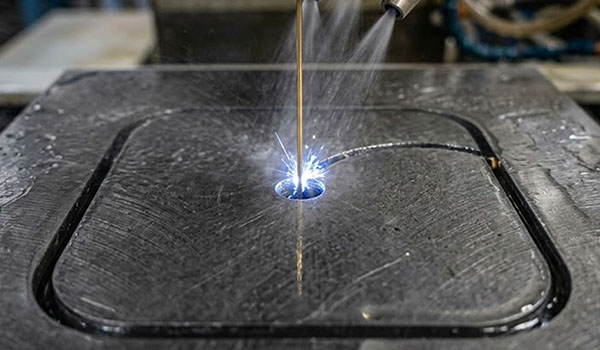
Start holes.
Wire EDM requires a start hole for internal features (slots, pockets, profiles that are not open-ended). Each additional start hole is a separate EDM drilling operation, typically adding 20–40 minutes per hole depending on material and diameter. Consolidating internal features to share start holes where geometry allows reduces cost.
Design Checks Before You Send Your Files
Run through this list before submitting Wire EDM files. Catching these issues before quoting saves a revision cycle.
- Confirm material is electrically conductive.Wire EDM cannot process non-conductors — ceramics, PEEK, glass, most plastics. If your material is a ceramic-metal composite, check conductor fraction with your supplier before assuming Wire EDM viability.
- Specify start hole locations for all blind internal features.Mark start holes on your drawing or 3D model. If start hole placement matters for part integrity (near edges, near stress risers), call out the constraint. Do not leave start hole location to supplier discretion on critical parts.
- Check minimum corner radius against your wire diameter.If your drawing calls for a 0.1mm internal corner radius, verify your supplier can run 0.15mm or smaller wire. Default wire diameter in most shops is 0.25mm, which limits corner radius to ~0.15mm minimum.
- Flag thin wall sections.Walls under 0.3mm in height direction are at risk of deflection from the wire’s water jet flushing force — effectively zero cutting force, but non-zero flushing pressure. Walls under 0.5mm in the XY plane may vibrate during cutting. Both require discussion with your supplier on fixture and cutting strategy.
- Specify surface finish and tolerance per feature, not globally.A global ±0.005mm callout on a Wire EDM part with 40 features will cost 3× what a selective tolerance callout costs. Use GD&T to identify the features that matter.
- Confirm heat treatment sequence.For tool steel parts: stress relief → rough Wire EDM → hardening → finish Wire EDM produces better dimensional outcomes than hardening before any Wire EDM. If your supplier recommends skipping rough EDM before heat treat, ask for their distortion data on equivalent parts.
For complex Wire EDM parts, XMAKE’s free DFM review identifies start hole conflicts, tolerance inconsistencies, and material risks before a single spark is struck — reducing the chance of a first-article failure that costs more than the machining itself.
Conclusion
The decision to use Wire EDM comes down to three factors your drawing already answers: material hardness, corner geometry, and tolerance. If your part is hardened before machining, needs internal radii under 0.4mm, or requires feature tolerances tighter than ±0.01mm, Wire EDM is not an alternative — it is the correct process.
XMAKE operates Wire EDM in both fast and slow wire configurations with tolerances to ±0.005mm, material capability across tool steels, carbide, titanium, and Inconel, and lead times starting at 3 days — covering prototype inserts through production tooling without a supplier switch mid-program.
Ready to manufacture? Upload your design for a free DFM review at xmake.com.
Frequently Asked Questions
What is the tightest tolerance achievable with Wire EDM on tool steel?
With a fine wire (0.1–0.15mm diameter) and a 4-pass cut sequence, production Wire EDM on D2 or H13 tool steel routinely holds ±0.003mm on individual features in a single setup. Across a multi-feature die set with repositioning, ±0.005mm is the practical working tolerance for most shops. Tighter than ±0.003mm requires temperature-controlled environments and is uncommon outside of gauge manufacture.
What surface finish Ra can Wire EDM achieve without secondary grinding?
A 3-pass Wire EDM sequence (rough + semi-finish + skim) achieves Ra 0.4–0.6 µm on tool steel without any secondary operation. A 4-pass skim cut sequence on favorable materials reaches Ra 0.2–0.3 µm. These values are comparable to precision surface grinding and sufficient for most sealing surfaces, sliding fits, and tooling applications. Secondary grinding is only required when Ra below 0.1 µm is specified.
When is Wire EDM cheaper than CNC milling on the same part?
Wire EDM is cost-competitive with CNC milling when: (1) the material is hardened to over 45 HRC, where milling tool life drops sharply; (2) internal corner radii under 0.4mm are required; (3) multiple CNC setups would otherwise be needed to achieve feature positional accuracy. For a D2 die insert at 60 HRC with ±0.005mm slot tolerance, Wire EDM is typically 40–60% less expensive than the CNC mill + heat treat + re-machine sequence.
Does Wire EDM work for small production runs, or is it only for prototypes?
Wire EDM is equally effective at any volume. For tooling — punches, dies, extrusion dies, injection mold inserts — Wire EDM is the production process of record, not a prototype shortcut. For direct-use components (implants, aerospace brackets), Wire EDM is used at volumes from 1 to several thousand pieces. It does not benefit from volume the way injection molding does, but it has no tooling amortization cost — each part costs the same as the first.
What file formats are required for Wire EDM quoting?
Most Wire EDM suppliers accept DXF (2D profiles), DWG, STEP, and IGES for 3D parts with tapered features. For standard straight-cut profiles, a clean 2D DXF with layer separation for cut path, start holes, and reference geometry is the fastest path to an accurate quote. Include material specification, hardness state at time of machining, and tolerance callout per feature in the drawing notes — not just a title block entry.
How does Wire EDM affect part hardness?
Wire EDM does not heat the bulk of the part. The spark-affected zone is confined to a surface layer of 5–20 µm. Bulk hardness of hardened tool steel or carbide is unchanged. The recast layer at the surface may have different microhardness than the base material — relevant for wear contact surfaces but not for the part’s structural properties.