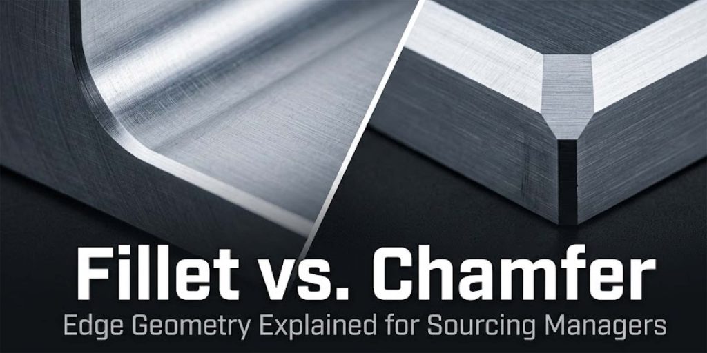
A fillet is a curved radius that blends two surfaces at a corner. A chamfer is a flat, angled cut that removes a corner entirely. Your drawing calls for one or the other on every functional edge — and when your supplier sends back a DFM note saying “internal radius too tight, recommend R3mm”, not knowing which is which means approving a change you can’t evaluate, or pushing back on one you shouldn’t.
This guide covers what each term means, where each belongs, and the vocabulary to use when a supplier flags an edge geometry issue on your order.
Fillet vs. Chamfer: A Quick Comparison
| Term | Shape | Described By | Primary Function | Typical Cost Impact |
|---|---|---|---|---|
|
Fillet |
Curved, concave or convex radius |
R + value (e.g. R3mm) |
Stress relief, material flow in molds |
Higher — requires ball-end mill, slower cut |
|
Chamfer |
Flat angled cut |
Distance × angle (e.g. 1.0mm × 45°) or C notation (e.g. C1) |
Assembly lead-in, deburring, weld prep |
Lower — single tool pass, minimal cycle time |
|
Break edge |
Minimal chamfer for deburring only |
0.2–0.5mm × 45° |
Remove machining burr, operator safety |
Negligible — standard included operation |
|
Sharp corner |
Unmodified 90° intersection |
None |
Rarely intentional — usually a drawing omission |
Risk of inspection failure, stress cracking |
What Is a Fillet?
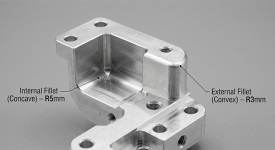
A fillet is a curved transition between two surfaces that replaces a sharp corner with a smooth radius. On a technical drawing, fillets are always called out with an R value: R2, R5, R10. The number is the radius of the curve in millimeters. A larger R value means a larger, more gradual curve.
Fillet typically appears in two forms: as an internal corner or as a rounded external edge.
An internal fillet (concave) sits inside a corner — at the base of a machined pocket, at the junction between a wall and a floor, or where a thinner section meets a thicker one.
An external fillet (convex) rounds over an outside edge and is more common in cast and injection-molded parts, where it serves cosmetic and mold-release purposes.
The defining characteristic of a fillet is continuity. The curve blends smoothly into both adjacent surfaces with no hard transition point. That continuity is exactly what makes fillets effective for structural applications.
What Is a Chamfer?
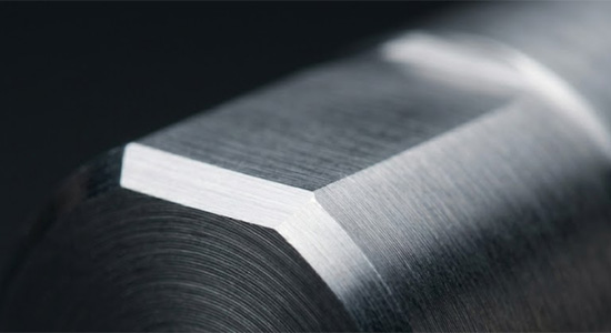
A chamfer is a flat angled cut that removes a 90° corner and replaces it with a single angled surface. Where a fillet blends continuously, a chamfer cuts decisively — it is a straight surface at a defined angle, not a curve.
On a drawing, chamfers are specified two ways. The full format is distance × angle: 1.5mm × 45° means the flat cut is 1.5mm wide at a 45° angle to both adjacent surfaces.
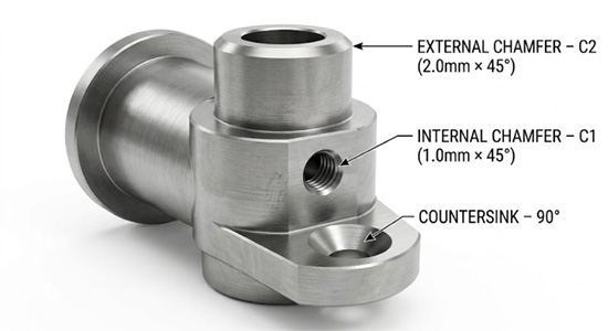
The shorthand format uses C notation: C1 means 1.0mm × 45°, C2 means 2.0mm × 45°. The C notation always assumes 45°. If the chamfer angle is anything other than 45°, the drawing must write the full format.
The 45° angle is standard for most assembly and deburring applications because it distributes the cut equally between both surfaces. Non-standard angles — 30°, 60°, 82° — appear in specific applications: countersinks for flat-head fasteners, valve seat geometry, and weld joint preparation.
What Is the Difference Between a Fillet and a Chamfer?
The difference is geometry, function, and cost — and all three are connected.
| Dimension | Fillet | Chamfer |
|---|---|---|
|
Geometry |
Curved radius — continuous blend |
Flat angled surface — single cut |
|
Drawing callout |
R value (e.g. R3) |
C notation or distance × angle (e.g. C1, 1.5 × 45°) |
|
Primary function |
Stress relief, mold flow, seal protection |
Assembly guidance, weld prep, deburring |
|
Machining method |
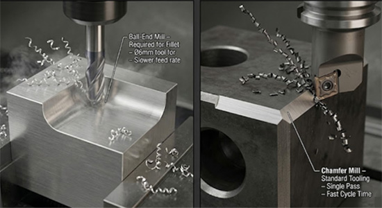
Ball-end mill — radius must match or exceed tool radius |
Chamfer mill — single pass, standard tooling |
|
Relative cost |
Higher — slower, specialty tooling for tight radii |
Lower — fast, standard tooling |
|
Best process fit |
Structural machined parts, castings, molded parts |
Assembled parts, threaded features, sheet metal |
|
Stress performance |
Reduces concentration by 30–40% at corners |
No stress relief — creates new transition edges |
|
Inspection |
Radius gauge or CMM |
Depth gauge or optical comparator |
What Does a Fillet Do?
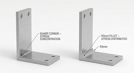
1.Fillets help reduce stress concentration.
At sharp internal corners, stress accumulates at the corner tip, making these areas highly susceptible to cracking. This is especially critical under cyclic loading, vibration, or thermal expansion, where cracks typically initiate at these points before propagating through the rest of the part.
A fillet distributes that stress across the curved surface. For example, an R3mm fillet on the internal corner of a 304 stainless steel bracket under cyclic load can reduce peak stress concentration by 30–40% compared to a 0.1mm sharp corner — a difference that directly affects fatigue life.
2.Better Flow in Corners
In injection molding and die casting, fillets serve a second function: they allow material to flow smoothly into corners during filling. A sharp internal corner in a mold creates turbulence in the melt flow and a stress riser in the mold steel itself.
Standard practice in injection mold design is a minimum internal fillet of R0.5mm on all non-parting-line corners — with R1mm or larger preferred for production tooling longevity.
Pro Tip-Fillet as a Quality Signal: If a machined structural part arrives with sharp internal corners and no fillet callout on the drawing, that is a drawing omission — not a supplier decision. The part may pass dimensional inspection and still fail in service. Structural corners on load-bearing aluminum or steel components should specify fillets explicitly.
What Does a Chamfer Do?
The primary function of a chamfer is to guide a mating part, fastener, or tool into position without requiring precise alignment on every insertion.
A C1 chamfer (1.0mm × 45°) on the entry of an M8 threaded hole allows the fastener to self-center as it engages the first thread. Without it, cross-threading probability increases significantly on production lines where operators insert hundreds of fasteners per shift. The chamfer is not structural — it is a handling and assembly efficiency feature.
On external features, a C2 chamfer on the end of a turned shaft guides it into a bearing housing or press-fit bore. The chamfer reduces insertion force and prevents galling at the entry point during press fitting.
Chamfers also serve as weld prep. A 1.5mm × 30° chamfer on the edge of a steel plate creates the V-groove geometry required for a full-penetration butt weld per ISO 9692 weld joint preparation standards.
Pro Tip — The Deburring Default: Suppliers apply a break edge chamfer (0.2–0.5mm × 45°) to all exposed sharp edges as a standard deburring step. This is included in base machining price and is not the same as a functional chamfer. If your drawing requires a specific chamfer size for assembly, call it out explicitly — “break edge” is not sufficient specification for functional edge geometry.
When to Use a Fillet?
Use a fillet when the design requirement is structural performance, material flow, or smooth surface continuity. The decision is driven by function, not aesthetics. Here are common applications of fillet :
1.Structural machined parts
Any internal corner on a bracket, frame, housing, or fixture that sees mechanical load should carry a fillet. The minimum practical fillet for CNC-machined 6061-T6 aluminum structural components is R3mm. Below R3mm, tooling cost increases and the stress relief benefit diminishes.
2.Cast and die-cast metal parts
Aluminum and zinc die castings require fillets on internal corners for mold fill and ejection. A sharp corner in a die-cast A380 aluminum tool creates premature die wear and surface defects on the cast part. Fillets are not optional in casting design — they are part of the process requirement.
3.Injection-molded plastic parts
All internal corners should have a minimum R0.5mm fillet. For structural plastic components in PC (polycarbonate) or PA6-GF30 (glass-filled nylon), a larger fillet of R1–R2mm reduces sink marks and internal stress at corners during cooling.
When to Use a Chamfer
Use a chamfer when the requirement is assembly guidance, weld preparation, or basic deburring on non-structural edges. Chamfers are the lower-cost, faster-to-machine option when structural performance is not the design driver.
Chamfers are widely applied in engineering design to improve functionality and manufacturability. Common applications include:
1.Non-functional exposed edges
A C0.5 break edge on all exposed edges is sufficient for parts that have no assembly or structural requirement at those edges. This prevents handling injuries and satisfies most quality inspection requirements for edge condition.
2.Bolt holes and threaded features
A C1 chamfer on every threaded hole entry is standard practice on CNC-machined parts. It prevents cross-threading, reduces assembly time, and adds negligible machining cost.
3.Shaft and pin lead-ins
any shaft entering a bore, bushing, or bearing should carry a C1.5–C2 chamfer on the insertion end. This is non-negotiable on interference fits where insertion force is high.
4.Weld joint preparation
Butt welds on steel plate 6mm and thicker require chamfered edges to achieve full weld penetration. The specific angle depends on the joint type and welding process.
5.Countersinks
A countersink is a chamfer applied to the entry of a hole to recess a flat-head fastener.
Advantages and Disadvantages of Fillets
Advantages:
- Eliminates sharp internal edges that cause handling injuries during assembly.
- Reduces stress concentration at corners, which can improve fatigue life in structural parts.
- Improve mold filling and facilitate part ejection in casting and injection molding
- Enhance surface finish continuity on machined parts.
Disadvantages:
- Adds mold complexity: Very tight fillet radii (R0.3mm and below) in injection mold steel require EDM finishing, adding tooling cost and lead time.
- Higher machining cost :An internal fillet requires a ball-end mill with a radius equal to or smaller than the specified R value. Tighter radii require more tool passes and slower feed rates — on a complex 5-axis CNC pocket with multiple R1mm corners, machining time can be 20–35% longer than the same pocket with R3mm corners
Advantages and Disadvantages of Chamfers
Advantages
- Low machining cost: a chamfer mill removes the corner in a single pass, with no tool changes. On a CNC milling center, adding chamfers across all hole entries on a part typically adds under 30 seconds of cycle time.
- Precise and repeatable: the flat surface is easier to inspect dimensionally than a radius, and tolerances of ±0.1mm on chamfer depth are achievable without special gauging.
- Works on any CNC operation : milling, turning, drilling, and laser cutting all produce chamfers with standard tooling and no specialty equipment.
Disadvantages
- No stress relief: a chamfer does not effectively distribute stress across a transition. At the edges of the chamfered flat, sharp transitions remain, creating stress concentration points that can lead to crack initiation and reduced fatigue life.
- Not suitable for mold design : a chamfered internal corner in an injection mold or die cast tool creates ejection problems and parting line complexity. Fillets are required in molded part design.
How to Determine Whether You Need a Fillet or a Chamfer
The decision follows the function of the edge. Ask four questions in sequence:
1.Is this corner load-bearing?
If the part carries mechanical load and the corner is in the load path — bracket, frame, housing wall, boss base — specify a fillet. Minimum R3mm for CNC-machined aluminum or steel.
2.Is this part cast, die-cast, or injection-molded?
If yes, all internal corners need fillets by default. Sharp internal corners in mold tooling cause premature tool wear, flow defects, and ejection problems. Your supplier’s DFM review will flag any sharp corners in a molded design — accepting the fillet recommendation is almost always correct.
3.Is this an assembly interface?
If the edge is where a fastener enters, a shaft inserts, or two mating parts align, specify a chamfer. Size it to the assembly requirement: C0.5 for light guidance, C1 for standard threaded holes, C2 for press fits and shaft lead-ins.
4.Is the edge non-functional?
If the edge carries no structural load and has no assembly function, a break-edge chamfer (C0.5) is sufficient. It satisfies quality inspection and prevents handling injuries without adding machining cost.
For sourcing managers, the practical takeaway is this: when a supplier flags an edge geometry issue in a DFM review, the question to ask your engineering team is not “can we keep it as-is?” but “what is the functional requirement at that edge?” The answer to that question tells you whether a fillet or chamfer belongs there — and whether the supplier’s recommendation is a cost-saving change or a structural compromise.
Conclusion
The choice between a fillet and a chamfer is a functional decision, not an aesthetic one. Fillets belong on structural corners, cast and molded features, and sealing interfaces — anywhere material stress, flow behavior, or seal integrity determines part performance. Chamfers belong on assembly interfaces, weld joints, and non-structural edges — anywhere the goal is faster insertion, cleaner thread engagement, or basic deburring.
XMAKE operates 500+ CNC machines in Shenzhen with tolerances to ±0.01mm. Our engineering team processes over 100000 technical drawings and provides free DFM analysis on every uploaded design — flagging fillet radius conflicts, missing chamfers on threaded features, and sharp corners in mold designs before production begins.
On a typical CNC aluminum part, changing an under-specified R0.5mm internal fillet to R3mm after DFM review reduces per-part machining cost while maintaining the structural intent of the design. Catching that at the DFM stage costs nothing. Catching it after first articles adds rework, delay, and in some cases retooling.
Ready to manufacture? Upload your design for a free DFM review at xmake.com.
Frequently Asked Questions
What is a fillet in manufacturing?
A fillet is a curved radius that blends two surfaces at a corner. It is specified on drawings with an R value — R2, R5, R10 — indicating the radius in millimeters. Fillets are used on structural parts to reduce stress concentration, on cast and molded parts to improve material flow and ejection, and on sealing interfaces to protect elastomeric seals from sharp edges.
What is a chamfer in manufacturing?
A chamfer is a flat angled cut that removes a 90° corner. It is specified as distance × angle (e.g. 1.5mm × 45°) or in C notation (e.g. C1 = 1.0mm × 45°). Chamfers guide fasteners into threaded holes, allow shafts to enter bores without galling, prepare edges for welding, and remove machining burrs from non-functional edges.
Can a chamfer replace a fillet for stress relief?
No. A chamfer removes material at a fixed angle but does not smooth the stress transition the way a radius does. At the two edges of the chamfer flat, new stress concentration lines are created. For load-bearing corners on metal parts, a fillet is the correct specification. Substituting a chamfer at a structural corner may satisfy dimensional inspection while creating a fatigue failure risk in service.
Why does a tight fillet radius cost more to machine?
The cutting tool used to machine an internal fillet must have a radius equal to or smaller than the specified fillet. An R1mm fillet requires a 2mm diameter ball-end mill — a fragile, slow-cutting tool that wears quickly. Specifying R3mm or larger allows larger-diameter tools, faster feed rates, and fewer passes. On a complex aluminum pocket with multiple internal corners, the difference between R1mm and R3mm can be 20–35% in machining cycle time.
What does "break edge" mean on a drawing?
Break edge means apply a minimal chamfer — typically 0.2–0.5mm × 45° — to remove the sharp burr left by cutting tools. It is a standard deburring operation included in base machining price. Break edge is not a functional specification. For bolt holes, threaded features, press-fit shafts, or structural corners, an explicit chamfer or fillet callout is required.
Do fillets and chamfers apply to sheet metal parts?
Both apply, with process constraints. Chamfers on laser-cut sheet metal edges are low-cost — the laser path angle changes to cut the chamfer. Fillets on sheet metal refer to bend radii, which are constrained by material and tooling. The minimum inside bend radius for 2mm thick 5052-H32 aluminum sheet is approximately 2.5mm — specifying a tighter bend radius causes cracking at the bend. This is a process limit, not a design preference.
What happens if edge treatment is not specified on a drawing?
The supplier defaults to break-edge deburring on all exposed edges. For non-functional surfaces, this is acceptable. For bolt holes, threaded features, structural corners, and assembly interfaces, an unspecified edge is a drawing omission. It can result in first-article inspection failures, assembly problems on the production line, or structural issues in service — none of which are the supplier’s responsibility if the drawing did not specify the requirement.